エネルギー効率
インバーターは高効率で知られているため、エネルギー損失を最小限に抑えてDC電力をAC電力に変換できます。 これにより、エネルギー料金を節約でき、二酸化炭素排出量を削減することもできます。
敏感な電子機器のための安全
インバーターはクリーンで安定した電力を生成するため、コンピューター、スマートフォン、テレビなどの機密性の高い電子機器で安全に使用できます。 多くの電子機器は電圧と周波数の変動に敏感であり、それらを損傷する可能性があるため、これは重要です。
バックアップ力
インバータは、停電の場合にはバックアップ電源として使用できます。 それらをバッテリーまたは他のDCソースに接続することにより、電源が再びオンになるまで、重要なアプライアンスおよびデバイスに電力を供給できます。 これは、緊急事態や自然災害時に特に役立ちます。
Table 1 Line Mode Specifications
| INVERTER MODEL | 7.2KW | 8.2KW | 10.2KW | |
| 5put Voltage Waveform | Sinusoidal (utility or generator) | |||
| Nominal Input Voltage | 230Vac | |||
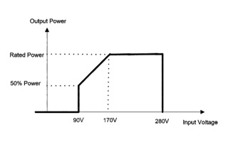
| Low Loss Voltage | 170Vac±7V (UPS); 90Vac±7V (Appliances) | |||
| Low Loss Return Voltage | 180Vac±7V (UPS); 100Vac±7V (Appliances) | |||
| High Loss Voltage | 280Vac±7V | |||
| High Loss Return Voltage | 270Vac±7V | |||
| Max AC Input Voltage | 300Vac | |||
| Nominal Input Frequency | 50Hz / 60Hz (Auto detection) | |||
| Low Loss Frequency | 40±lHz | |||
| Low Loss Return Frequency | 42±lHz | |||
| High Loss Frequency | 65±lHz | |||
| High Loss Return Frequency | 63±lHz | |||
| Output Short Circuit Protection | Circuit Breaker | |||
| Efficiency (Line Mode) | >95% ( Rated R load, battery full charged ) | |||
| Transfer Time | 10ms typical (UPS); 20ms typical (Appliances) | |||
| Output power derating: When AC input voltage drops to 170V, the output power will be derated. |  | |||
Table 2 Inverter Mode Specifications
| INVERTER MODEL | 7.2KW | 8.2KW | 10.2KW |
| Rated Output Power | 7.2KW | 8.2KW | 10.2KW |
| Output Voltage Waveform | Pure Sine Wave | ||
| Output Voltage Regulation | 230Vac±5% | ||
| Output Frequency | 50Hz | ||
| Peak Efficiency | 93% | ||
| Overload Protection | 3s@>150% load;5s@101%~150% load | ||
| Surge Capacity | 2* rated power for 5 seconds | ||
| Nominal DC Input Voltage | 48Vdc | ||
| Cold Start Voltage | 46.0Vdc | ||
| Low DC Warning Voltage | |||
| @ load < 50% | 44.0Vdc | ||
| @ load > 50% | 42.0Vdc | ||
| Low DC Warning Return Voltage | |||
| @ load < 50% | 45.0Vdc | ||
| @ load > 50% | 44.0Vdc | ||
| Low DC Cut-off Voltage | |||
| @ load < 50% | 41.0Vdc | ||
| @ load > 50% | 40.0Vdc | ||
| High DC Recovery Voltage | 62Vdc | ||
| High DC Cut-off Voltage | 63Vdc | ||
| No Load Power Consumption | 60W | 70W | 75W |
Table 3 Two Load Output Power
| INVERTER MODEL | 7.2KW | 8.2KW | 10.2KW |
| Full Load | 7200W | 8200W | 10200W |
| Maximum Main Load | 7200W | 8200W | 10200W |
| Maximum Second Load(battery model) | 2400W | 2733W | 3400W |
| Main Load Cut Off Voltage | 44VDC | ||
| Main Load Return Voltage | 48VDC | ||
Table 4 Charge Mode Specifications
| Utility Charging Mode | ||||||||
| INVERTER MODEL | 7.2KW | 8.2KW | 10.2KW | |||||
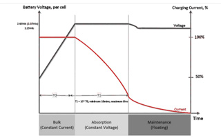
| Charging Algorithm | 3-Step | |||||||
| AC Charging Current (Max) | 140Amp | 140Amp | 160Amp | |||||
| Bulk Charging Voltage | Flooded Battery | 58.4 | ||||||
| AGM / Gel Battery | 56.4 | |||||||
| Floating Charging Voltage | 54Vdc | |||||||
| Charging Curve |  | |||||||
| MPPT Solar Charging Mode | ||||||||
| INVERTER MODEL | 7.2KW | 8.2KW | 10.2KW | |||||
| Max. PV Array Power | 8200W | 10200W | ||||||
| Nominal PV Voltage | 360Vdc | |||||||
| PV Array MPPT Voltage Range | 90Vdc~500Vdc | |||||||
| Max. PV Array Open Circuit Voltage | 500Vdc | |||||||
| Max Charging Current (AC charger plus solar charger) | 160Amp | 160Amp | 180Amp | |||||
Table 5 Grid-Tie Operation
| INVERTER MODEL | 7.2KW | 8.2KW | 10.2KW |
| Nominal Output Voltage | 220/230/240 VAC | ||
| Feed-in Grid Voltage Range | 195-253VAC | ||
| Feed-in Grid Frequency Range | 49-51 ±lHz/59~61±1 Hz | ||
| Nominal Output Current | 31.3A | 35.6A | 44.3A |
| Power Factor Range | >0.99 | ||
| Maximum Conversion Efficiency (DC/AC) | 98% | ||
Table 6 General Specifications
| INVERTER MODEL | 7.2KW | 8.2KW | 10.2KW |
| Safety Certification | CE | ||
| Operating Temperature Range | -10°C to 50°C | ||
| Storage temperature | -15°C~ 60°C | ||
| Humidity | 5% to 95% Relative Humidity (Non-condensing) | ||
| Dimension (D*W*H), mm | 537*390*130 | ||
| Net Weighty kg | 14.2 | 14.2 | 14.5 |